. Railway mechanical engineer . members, with every support board bolted inplace. On the inside of the car horizontal retaining stripsare attached to the sides to prevent the board from beingloosened from the frame by the pounding, which is often nec-essary to dislodge the coal in the car. The chute boards, be-side being supported at both ends and over the bolsters, areprovided with two intermediate supports attached to the sideplanking of the car by cast iron pockets of ample dimen-sions. The lower one is gained over the center sills, and theupper one is supported from the end sill by 6-in. b
Image details
Contributor:
Reading Room 2020 / Alamy Stock PhotoImage ID:
2CGYG1XFile size:
7.1 MB (271 KB Compressed download)Releases:
Model - no | Property - noDo I need a release?Dimensions:
1920 x 1301 px | 32.5 x 22 cm | 12.8 x 8.7 inches | 150dpiMore information:
This image is a public domain image, which means either that copyright has expired in the image or the copyright holder has waived their copyright. Alamy charges you a fee for access to the high resolution copy of the image.
This image could have imperfections as it’s either historical or reportage.
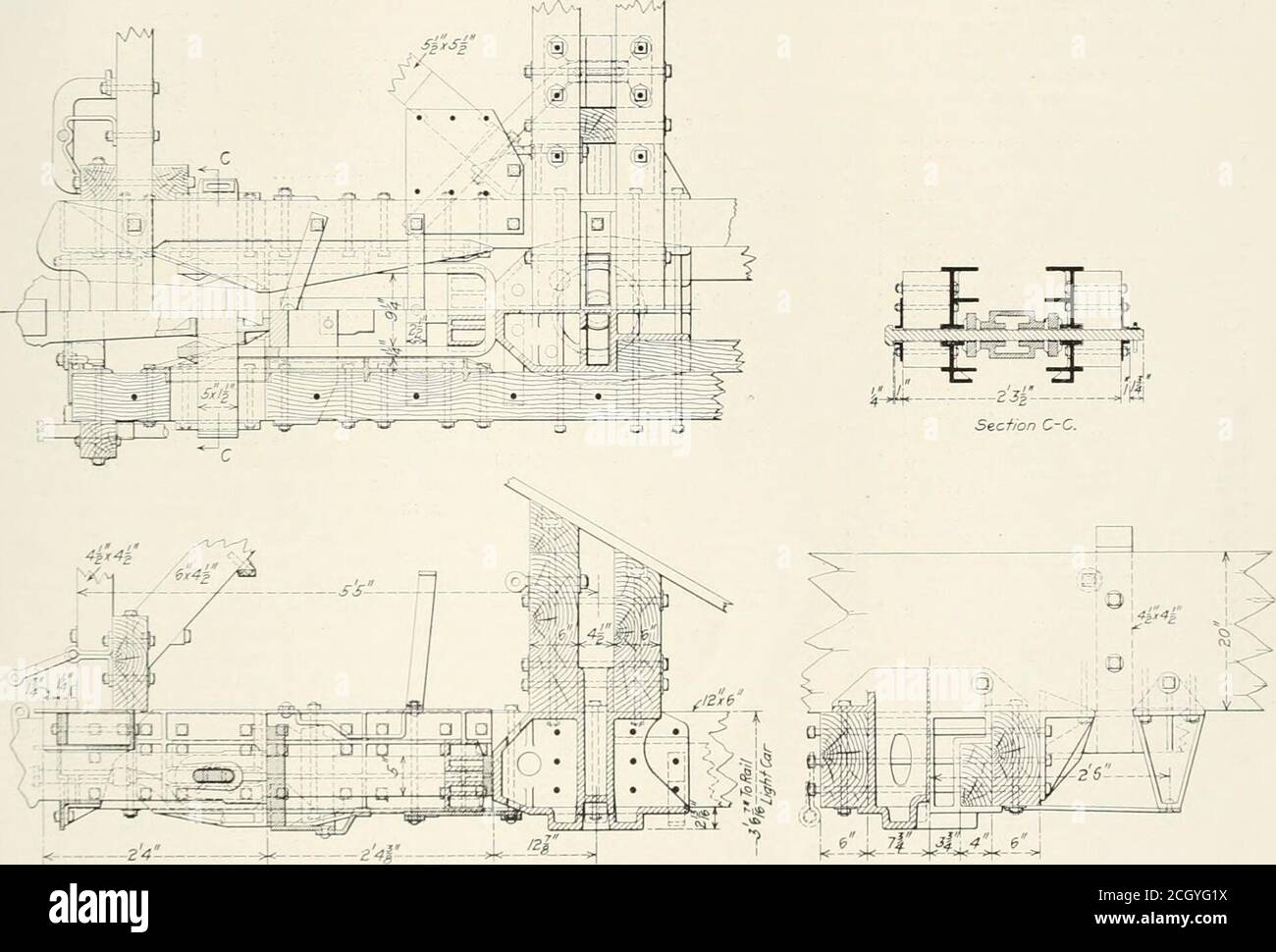
. Railway mechanical engineer . members, with every support board bolted inplace. On the inside of the car horizontal retaining stripsare attached to the sides to prevent the board from beingloosened from the frame by the pounding, which is often nec-essary to dislodge the coal in the car. The chute boards, be-side being supported at both ends and over the bolsters, areprovided with two intermediate supports attached to the sideplanking of the car by cast iron pockets of ample dimen-sions. The lower one is gained over the center sills, and theupper one is supported from the end sill by 6-in. by 4-in.diagonal struts. Beneath the chute are two diagonal trussrods, each running from the top of the chute at one side ofthe car to the bottom of the chute at the other side. Thechute is thus in effect a diagonal transverse truss which holdsthe side frames securely in alignment, and resists any tend-ency towards weaving of the whole structure. The sides ofthe car are tied together at the top by five J^-in. cross bolts. rAA-^1. ^- 24- ^. Draft Gear and Bolster Details 7 ^^j^^^J^j^M Railway Appliance Company and is the same as that usedon the 100-ton steel hopper coal cars of tlu- Norfolk &Western.* If will be seen that the arrangement of the doors is suchthat half of the load at the inside of the dw)rs is carried liythe center sills and half by the side sills, while the total loadat the swinging side of the doors is supported by the sidesills. The center sills thus support one-(|uarter of the totalload resting on the door, and this is in turn tran.smitted tothe side frames through the bolsters and the needle beam atthe center of the car. The siding and chutes are made of ship lapped material1 5/16 in. thick. The .siding is applied vertically and spiked Sec the Railvny MecharJcal Engineer for February, 1918, page 96. IIk- .design of the car is characterized by tlie extent towhich use has been m.ide of pockets and corner castings ofliberal dimensions for the connection of the va