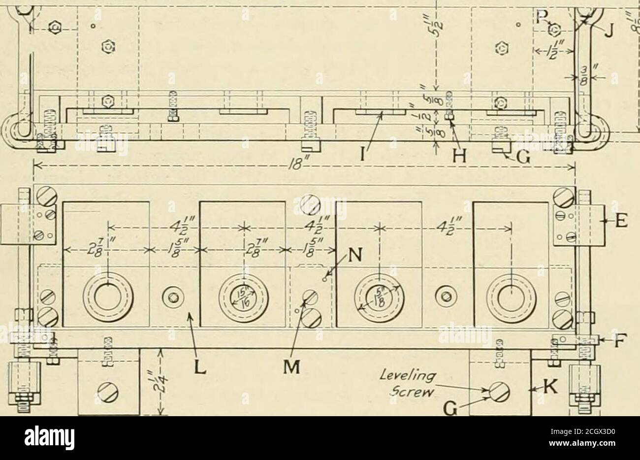
. Railway age gazette . ndition. The construction is simple and inexpensive so far as materialis concerned. It was made from two pieces of J4 in- by 5 in. by6 in. angle, each 18 in. long. These angles, which are shown atL in the illustration, were machined all over with a 4 in. endmill on a large milling machine. They are held together bymeans of two cast iron cross bars and machine screws O; thecross bars are shown at A. On each side of the jig are eighthardened tool steel leveling screws G, which were ground on asurface grinder after being applied to the jig. Two leveling barsA were made fro

Image details
Contributor:
Reading Room 2020 / Alamy Stock PhotoImage ID:
2CGX3D0File size:
7.1 MB (264.6 KB Compressed download)Releases:
Model - no | Property - noDo I need a release?Dimensions:
1961 x 1274 px | 33.2 x 21.6 cm | 13.1 x 8.5 inches | 150dpiMore information:
This image is a public domain image, which means either that copyright has expired in the image or the copyright holder has waived their copyright. Alamy charges you a fee for access to the high resolution copy of the image.
This image could have imperfections as it’s either historical or reportage.
. Railway age gazette . ndition. The construction is simple and inexpensive so far as materialis concerned. It was made from two pieces of J4 in- by 5 in. by6 in. angle, each 18 in. long. These angles, which are shown atL in the illustration, were machined all over with a 4 in. endmill on a large milling machine. They are held together bymeans of two cast iron cross bars and machine screws O; thecross bars are shown at A. On each side of the jig are eighthardened tool steel leveling screws G, which were ground on asurface grinder after being applied to the jig. Two leveling barsA were made from machine steel and each held in place by threescrews .1/, together with three of the leveling screws. Aftersecuring the leveling bars to the jig, it was placed on a millingmachine and the jig holes drilled by using the micrometer at-tachment. Accuracy in locating the holes was thus obtained.Four hardened and ground tool steel bushings / were thenpressed into the holes in each bar. Perfect alinement of the bars ^if:^-T^. ^s-^^ Leveling f- V-2-A V-l-A