Engineering and Contracting . panel of 25 ft. or of more than onelor panels of ordinary size. Effect of Raising Lower Chord at Centerof Span.—Trusses of like dimensions were designed, excepting that tlie lower chordwas raised o, 5, 10, 15, 20 and 25 ft. re-spectively at the center of span, the rise otupper chord being 50 ft. The results arcgiven in Fig. 8. The dotted line D repre-sents the weights of trusses of equal deptliat the center but having a horizontal lowerchord and supporting smaller normal windpressures on account of their lesser inclina-tions. The weight of covering, sheathing, raf
Image details
Contributor:
The Reading Room / Alamy Stock PhotoImage ID:
2AJBMWAFile size:
7.2 MB (290.8 KB Compressed download)Releases:
Model - no | Property - noDo I need a release?Dimensions:
1048 x 2385 px | 17.7 x 40.4 cm | 7 x 15.9 inches | 150dpiMore information:
This image is a public domain image, which means either that copyright has expired in the image or the copyright holder has waived their copyright. Alamy charges you a fee for access to the high resolution copy of the image.
This image could have imperfections as it’s either historical or reportage.
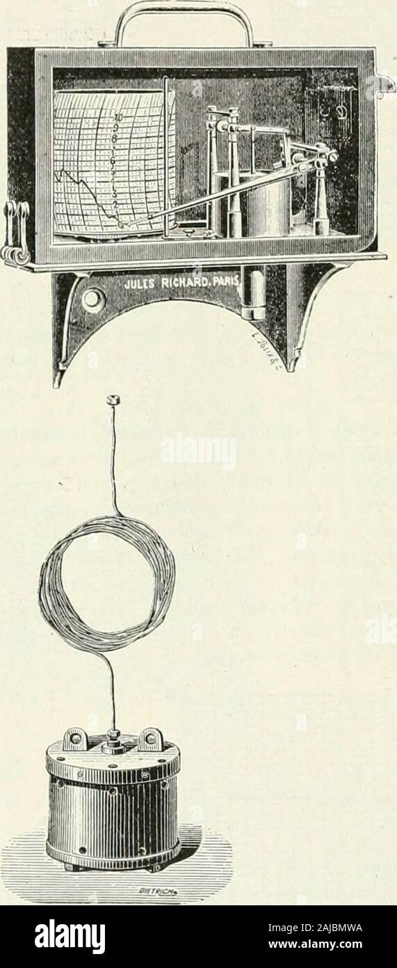
Engineering and Contracting . panel of 25 ft. or of more than onelor panels of ordinary size. Effect of Raising Lower Chord at Centerof Span.—Trusses of like dimensions were designed, excepting that tlie lower chordwas raised o, 5, 10, 15, 20 and 25 ft. re-spectively at the center of span, the rise otupper chord being 50 ft. The results arcgiven in Fig. 8. The dotted line D repre-sents the weights of trusses of equal deptliat the center but having a horizontal lowerchord and supporting smaller normal windpressures on account of their lesser inclina-tions. The weight of covering, sheathing, raft-ers and purlins remains constant; theweights of trusses and of roofs both in-crease rapidly with the rise of lower chord.A comparison of curves D and E showsclearly that this raising or cambering ofthe lower chord is not economical and isdone only for effect. Most Economical Ratio of Rise to Span practically one-sixth the span, identicalwith the ratio for ordinary bridge trusses.Hence the best rise is one-sixth the span.. Automatic Recording Water Gage. of Truss.—A series of trusses of 200-ft.span and set 20 ft. apart was also designedand computed for rises of 20, 25, 30, 35, 40, 45 and 50 ft. respectively in order to deter-mine the best proportion of rise to span.The results are plotted in Fig. 9. As therise increases, the weights of covering, sheathing, rafters and purlins slightly in-crease ; also the additional weight of theconnections. The weight of trusses andthat of the roof diminish, each being aminimum for a rise of 35 ft., which is A Recording Water Gage for Rivers, Reservoirs, Tanks, Boilers, Etc. W c illustrate herewith one of severaltypes of automatic recording gages for reg-istering the surface height of water. Thisparticular gage may be mounted any dis-tance within 300 ft. of the reservoir, tankor river. A small copper tube transmitsthe air pressure that actuates the leverupon which is mounted the recording pen.The cylindrical iron box from which thiscopper pi