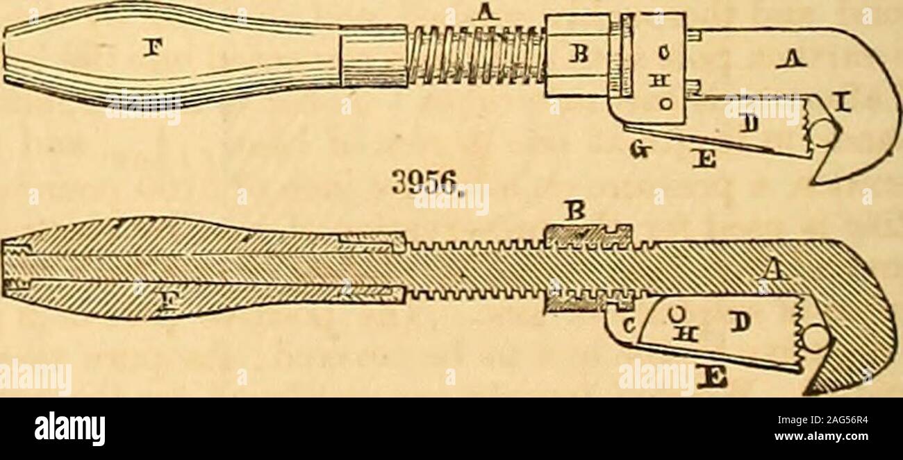
. Appleton's dictionary of machines, mechanics, engine-work, and engineering. ds the main bar. The circular end of the lever is also indented or roughened that it maynot slip on the cylinder I. H, joint of the lever D and slide C ; I, the cylindrical substance to be turned. To operate the wrench, it is placed upon the cylinder to be turned, as seen in Fig. 3955, and theindented end of the lever D is brought in contact with it by means of the nut B. The handle is thenmoved backwards, and the lever advanced at the same time, until the end of the lever is somewhatraised from the main bar ; the ha
Image details
Contributor:
The Reading Room / Alamy Stock PhotoImage ID:
2AG56R4File size:
7.2 MB (263.2 KB Compressed download)Releases:
Model - no | Property - noDo I need a release?Dimensions:
2381 x 1050 px | 40.3 x 17.8 cm | 15.9 x 7 inches | 150dpiMore information:
This image is a public domain image, which means either that copyright has expired in the image or the copyright holder has waived their copyright. Alamy charges you a fee for access to the high resolution copy of the image.
This image could have imperfections as it’s either historical or reportage.
. Appleton's dictionary of machines, mechanics, engine-work, and engineering. ds the main bar. The circular end of the lever is also indented or roughened that it maynot slip on the cylinder I. H, joint of the lever D and slide C ; I, the cylindrical substance to be turned. To operate the wrench, it is placed upon the cylinder to be turned, as seen in Fig. 3955, and theindented end of the lever D is brought in contact with it by means of the nut B. The handle is thenmoved backwards, and the lever advanced at the same time, until the end of the lever is somewhatraised from the main bar ; the handle is then carried forward in the direction shown by the arrow, whichcauses the lever to take firm hold of the cylinder and carry it around in the same direction ; and byreversing the motion of the handle, the cylinder is instantly released for a new hold. It will be ob-vious that the wrench can be readily adapted to any size of cylinder within its compass, and will thue6upply the place of a pair of tongs (the only tool in use for the same purpose previous to this inven-. ZINC. 957 3957. ? p 6 ftOP n ?3—__a:d 1/ tion) for each particular size of cylinder. It also possesses the advantage of being worked with on*hand after being set to the particular size required. WRENCH, SCREW. Invented by S. Merrick, of Springfield, Massachusetts, and patented Au-gust 17, 1835 ; patent extended May 14, 1849. In the drawings, Fig. 3957 denotes a side ele-vation ; Fig. 3958, a vertical central section.The same letters refer to like parts in eachfigure. A is the main bar; B, the nut fitted to ascrew, cut on the two opposite edges of themain bar; C, a strap, which passes around in agroove formed in the nut B, and is riveted tothe end of the slide-jaw D. The collar on theend of the nut B takes into a correspondinggroove in the slide D; E, the end of the mainbar, which forms the stationary jaw of thewrench; F, the handle. The nut is made tomove freely in the strap C, and, by turning it tothe rig