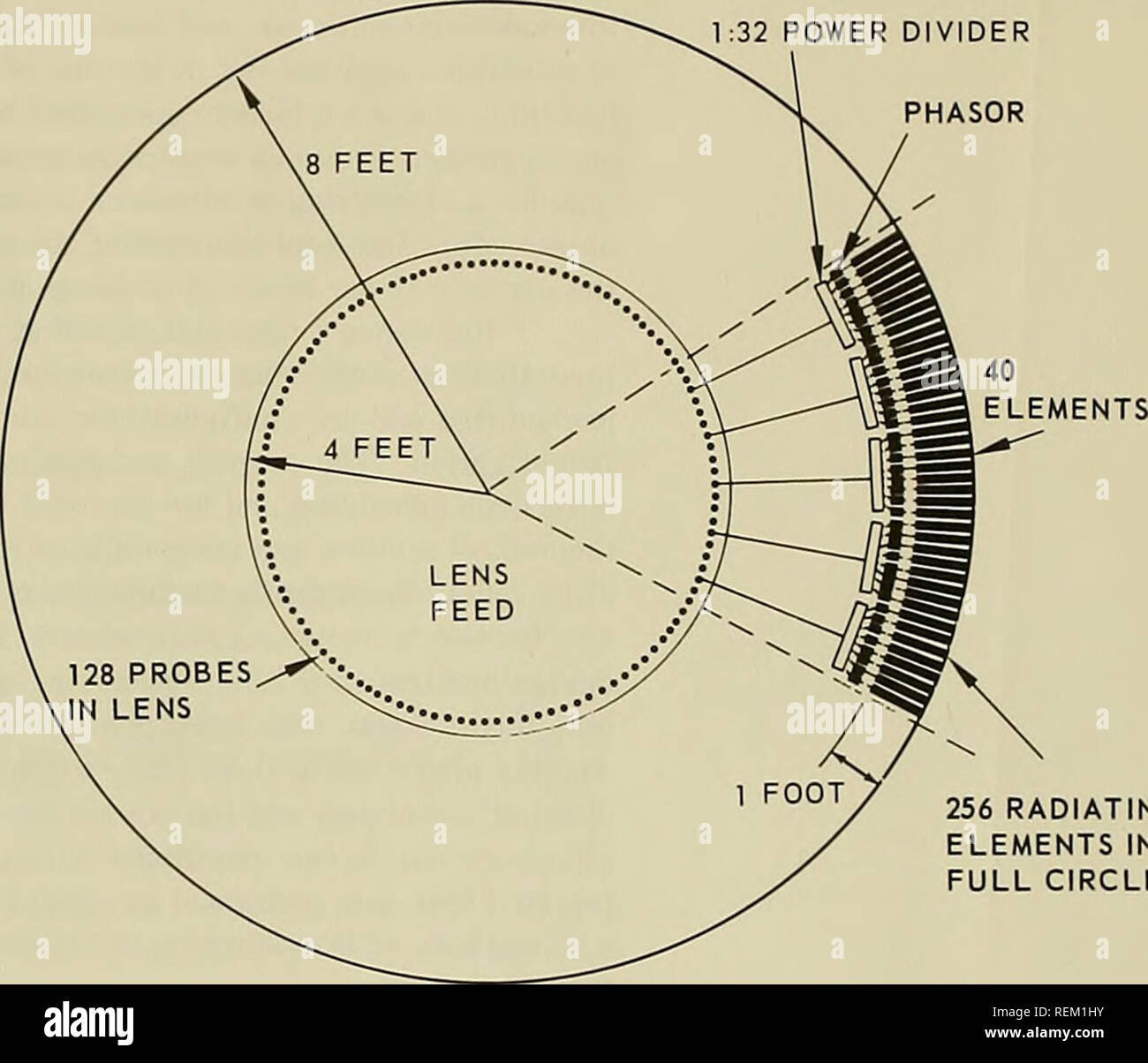
. Circular-array radar antenna : Pencil-beam forming and phasing techniques. Radar; Antennas (Electronics). EQUAL-LENGTH CABLES 40 ELEMENTS PER ROW 32 ELEMENTS PER COLUMN A. SECTION VIEW 1:32 POWER DIVIDER PHASOR. 256 RADIATING ELEMENTS IN FULL CIRCLE B. LENS AND TOP VIEW OF RADIATING ARRAY Figure 1. Sectional and top views of cylindrical array.. Please note that these images are extracted from scanned page images that may have been digitally enhanced for readability - coloration and appearance of these illustrations may not perfectly resemble the original work.. Provencher, J. H; Munger, A. D
Image details
Contributor:
The Book WormImage ID:
REM1HYFile size:
7.1 MB (203.2 KB Compressed download)Releases:
Model - no | Property - noDo I need a release?Dimensions:
1707 x 1464 px | 28.9 x 24.8 cm | 11.4 x 9.8 inches | 150dpiMore information:
This image is a public domain image, which means either that copyright has expired in the image or the copyright holder has waived their copyright. Alamy charges you a fee for access to the high resolution copy of the image.
This image could have imperfections as it’s either historical or reportage.
. Circular-array radar antenna : Pencil-beam forming and phasing techniques. Radar; Antennas (Electronics). EQUAL-LENGTH CABLES 40 ELEMENTS PER ROW 32 ELEMENTS PER COLUMN A. SECTION VIEW 1:32 POWER DIVIDER PHASOR. 256 RADIATING ELEMENTS IN FULL CIRCLE B. LENS AND TOP VIEW OF RADIATING ARRAY Figure 1. Sectional and top views of cylindrical array.. Please note that these images are extracted from scanned page images that may have been digitally enhanced for readability - coloration and appearance of these illustrations may not perfectly resemble the original work.. Provencher, J. H; Munger, A. D; Naval Electronics Laboratory Center. San Diego, Calif. : Naval Electronics Laboratory Center